|
Monitoring alarms and operating parameters is an important part of any facilities management program. Many options are available for monitoring emergency or primary power. Main topics covered are:
• Monitoring Engine and Generator set
• Control Panel Options
• Options for Remote Monitoring
Monitoring Engine and Generator Set
Many options are available to allow facilities manager or owner to monitor and interface with the standby or primary power generator set. Monitoring engine parameters allows for early diagnosis of developing problems. Repairing issues before they advance to shut-down failures will result in raising the reliability of both emergency and primary power systems. Basic configurations outlined below:
• Generator sets with engines that are not controlled by an ECM (Electronic Control Module). Older Generator sets are older (1990’s and prior). Monitoring capabilities limited to analog converted to digital signal via an A to D converter. Basic generator set parameters can be monitored, referred to as “Historic Generator Sets”.
• ECM controlled generator sets. Common manufacturer practice is to incorporate a generator control module (monitors generator parameters) and engine control module (monitors engine parameters) into one operating system. This configuration allows for advanced parameter monitoring and control referred to as “Advanced Generator Sets”.
• New generator sets with advanced control panels.
Historic Generator Sets
The basic theory of operation for a diesel engine remains unchanged. Historic generator sets often have low hours and are completely reliable. Often these generator sets were replaced because of the inability to supply advanced information to facilities managers. If facility requirements do not require an advanced alarm and monitoring system Historic Generators Sets are a viable solution. Utilization of an aftermarket monitoring and control system can be employed to monitor and control:
The basic engine and generator functions can be easily monitored with this configuration are:
• Engine oil pressure.
• Engine coolant temperature (providing radiator has port for aftermarket sensor installation).
• Engine RPM (Revolutions per Minute).
• Generator voltage.
• Generator amperage.
• Compartment louver position and control (depending on hardware manufacturer).
• Compartment temperature (depending on hardware manufacturer).
To accomplish the monitoring and control functions, often aftermarket suppliers are used. Single or Multiple Generator applications can be monitored utilizing an aftermarket supplier. Reputable vendors supply product that comply with SAE (Society of Automotive Engineers) and other state and government agencies.
If a single generator configuration is needed to maintain power requirements for a facility or home the below listed configuration can be utilized. Gen-Tracker generator monitoring system is an option for monitoring the generator. In the below configuration the panel has the ability to perform the following time stamped functions:
• Monitor three voltage sensor inputs (Normal, Emergency and Load). Generator (switch panel) to Gen-Tracker communication.
• Four digital sensor inputs (such as oil pressure, coolant level, low fuel pressure and high coolant temperature). Engine to Gen-Tracker Communication.
• Engine starter contact status. Engine to Gen-Tracker communication.
• Fail to exercise. Software within Gen-Tracker unit (programmable) allow alarms when predetermined events do not occur according to plan. Can send event to land line, cellular, WIFI and Ethernet.
• Two fuel level inputs 5-20 V and 4-20 ma. Select one depending on fuel level style.
• Battery condition monitoring (float and cranking voltage).
• Remote starts and generator status.
Panel Considerations
Some considerations should be made when selecting the generator monitoring system for an application. Below are some items to consider:
• Capability of monitoring system – Will the selected system meet all monitoring and communication needs, and allow for future growth?
• Points to monitor on generator engine – These are digital inputs. Digital inputs or in the ON or OFF state. Some styles of these switches are high or low level switch, high or low pressure switches and high or low pressure switches.
• Selection of fuel tank level monitor. Two choices available 5 to 20 V and 4 to 20 ma. The 4 to 20 ma level monitors are widely used and considered more accurate.
A sample of a circuit card is provided to illustrate the capability of monitoring unit circuit cards. At a glance a technician can see if the system is operating correctly or aid in problem isolation.
• DS1 COM – Solid lamp indicates unit is communicating with device (phone, network etc.).
• DS2 SIGNAL – Solid lamp indicates unit is waiting to transmit signal.
• DS3 FAULT – Solid lamp indicates generator faulted.
• DS4 HEARTBEAT – Blinking one second intervals, unit is OK.
• DS5 SPEED – Network speed on solid with 100Mbit and off if 10 Mbit connection.
• DS6 LINK – Solid lamp indicates linked to network.
• DS7 START CONTACT – Solid lamp indicates starter contacts open, off indicates closed.
• DS8 RELAY STATUS - Indicates if relay is energized or de-energized
ECM Controlled Engines without Advanced Control Panels
A large advancement in diesel technology was the advent of the ECM. Called engine control module or electronic control module depending on the manufacturer. The ECM controls all engine functions via software and hardware. Hardware is classified into two main types:
• Input – Any device that provides an input signal to the ECM. Some signals considered input are temperature, pressure, speed, and position.
• Output – Any device that action is controlled by the ECM. Some of these devices are engine starter, light emitting diodes and digital signals to gauges, turbocharger control valve signals and injector fire signals.
The software in the ECM allows advanced monitoring functions. It can be accessed using a laptop and the proper adapter connected to a 9-pin data link connector. The connector is generally at the operator panel for the engine. Once connected engine parameters, some set points (excluding calibration), alarms and history can be accessed.
Each ECM has interface software. Most commonly a SAE J1939 datalink with a SAE J1587 as a backup. The datalink circuit is the digital communication link between engine ECM and Remote Monitoring System.
To accomplish remote monitoring of both engine and generator functions of a generator set, an additional control panel must be used. When selecting the control panel consider the following.
• To monitor all engine functions, panel must have J1939 connections and software.
• Does panel have OEM harness available for different manufacturers.
• Mounting hardware and connecting cables included.
• Software package is installed in the panel.
• Panel wiring connection options.
A connection example using a Panelsource P10 CAN BUS is used as the example controller. The configuration is as follows:
• Generator is connected to an automatic transfer switch.
• Generator start function connected to automatic transfer switch panel.
• P10 control panel connected to Automatic Transfer switch for generator monitoring and engine start functions.
• P10 control panel connected to engine ECM via J1939 Datalink for alarm monitoring and ECM access via manufacturer software. ECM software interface with P10 software.
• Ethernet option is used to connect to computer or network.
• Phone option used to allow communication with VOIP (Voice Over Internet Protocol).
The Panelsource P10 offers advanced ECM monitoring and control functions. Facilities managers can decide what parameters they would like to remotely monitor and notifications received. All engine and generator parameters can be monitored from the Ethernet connected computer or display screen of the P10. Some common notifications outside operator space can be:
• Low output for generator voltage and amperage.
• Generator start command.
• Un-commanded generator shutdown (cause could be loss of fuel supply).
• Any fault code deemed as “Critical” by generator set manufacturer. If these fault codes are not solved, they can progress to ECM commanded limp mode or complete engine shutdown.
• Any fault code that results in reduced engine performance.
• Any fault code that results in engine shutdown.
ECM Controlled Engines with Advanced Control Panels
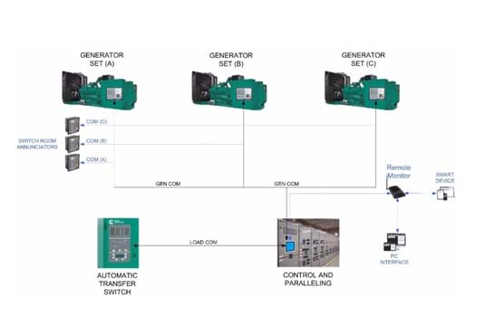
Generator sets that are ECM controlled with an advanced control panels offer many capabilities. All advanced monitoring functions are incorporated into one main panel (PCC 3300).The example below outlines three Cummins generators that have advanced control panels have been connected to a PCC 3300 controller. Connecting generators in this configuration will allow:
• Two emergency generators with one redundant supply.
• The panels are connected via SAE J1939 datalink for advanced monitoring options.
• Annunciators can be remotely into a separate room for monitoring.
• PCC 3300 controls all generator functions of all generators.
• PCC 3300 has the ability to parallel generators (Manual paralleling of load is not required).
• PCC 3300 has load sharing capabilities.
• System computer interface, remote monitoring via cell and smart device capabilities.
|